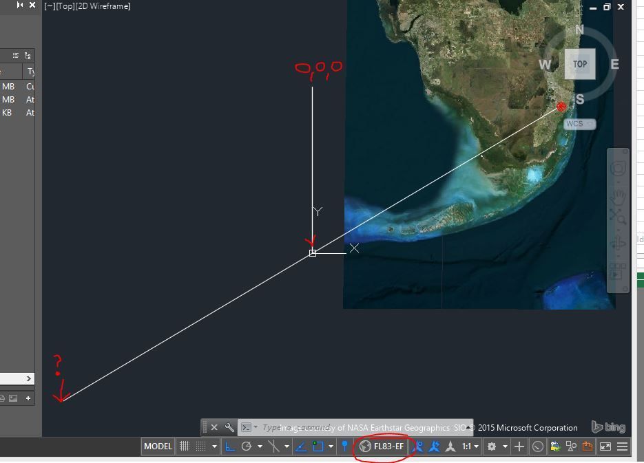


WCS is fixed in Autocad drawings. For our projects, if required we can create UCS to work with. In this case too, UCS is defined wrt WCS. So indirectly all we create is addressed with WCS. Its similar to Sun (WCS) is center of Solar system. But all items in earth can be addressed with earths center (UCS). Jan 29, 2012 The WCS origin is where the X and Y axes intersect (0,0). All objects in a drawing file are defined by their WCS coordinates. However, it is usually more convenient to create and edit objects based on the movable UCS. By default when you start a new (blank) drawing you use the World Coordinate System (WCS). This is your (0,0,0) point. Changing From UCS to WCS in AutoCAD. This workflow could be useful for Corridor projects or mapping that was received by outside. Agencies (Cities. Could somebody explain to me the differences between the UCS and WCS please.? In particular the (trans (0 0 0) 0 1) and (trans (0 0 0) 1 0). Differentiate Between Ucs And Wcs In Autocad Average ratng: 5,0/5 9447 reviews Coordinate system when referenced. It may be due to a User Defined Coordinated System (UCS) within AutoCAD which may need to be updated to a World Coordinate System (WCS). As an integer code that specifies the WCS, current UCS, or current DCS (of either the current viewport or paper space). As an entity name returned by one of the entity name or selection set functions. This specifies the OCS of the named object. If the OCS does not differ, conversion between OCS and WCS is an identity operation.
Differentiate Between Ucs And Wcs In Autocad Free
A question regarding converting angles between co-ordinate systems in AutoCAD .NET.
Im creating my first little utility to form selected block attribute references into a nice neat list. The current version takes a selection of blocks and a list insert location and then moves the attribute references to the location and rotates them to WCS angle of 0.
I now want to expand the program to make it a little more flexible and allow you to form the list parallel to the currently selected UCS x axis (the i.e. and angle of 0 in relation to current ucs's).
I have managed bumble my way through and transform the attribute positions correctly to form a list relative to the current UCS but am strugling on how to work out in code what the equivlanent WCS angle value would be.
I have done some calcs using .net framework to calculate an angle between two vectors (see code extract below). But this introduces a small error into the angles (i.e. if my ucs is set rotated 45 degrees around the zed and i use the below maths, the resulatant angle is 45.0000002 when read in acad afterwards).
Matrix3d ucsCur = ed.CurrentUserCoordinateSystem;
CoordinateSystem3d cs = ucsCur.CoordinateSystem3d;
// the below seems to work by calugulating the angle between two vetrex using .net maths class but this introduce a small accuracy error . Lenovo ideapad 320 drivers windows 10. Is there a better way?
Double rotAngle = Math.Acos((1 * cs.Xaxis.X) + (0 * cs.Xaxis.Y) + (0 * cs.Xaxis.Z));
//set the attribute reference rotation to the calculated WCS radian rotation value 'rotAngle'
attRef.Rotation = rotAngle;
Im sure there is a better way built into the managed autocad wrapper using a tranform matix and the ucs vertex information but dont really know how to go about it. Any links explaining how to work with the UCS in .net.
